Wednesday, July 28, 2021

How to Deal with the 9 Accidents in the Blast Furnace Production Process?

1. How to deal with sudden burning of air outlet and water cut?

The treatment scheme is as follows:

●  Stop the fuel injection at the air outlet quickly, spray water outside the air outlet for cooling, and arrange special personnel to monitor it to prevent burning out.

●  Change atmospheric operation or air release according to the situation.

●  Organize slag and iron out, prepare to stop air and replace it.

●  In order to reduce the leakage of water into the furnace, the wind should be reduced to strive for a bright tuyere before the wind is stopped, so as to prevent the tuyere from sticking to the iron and prolong the wind break time.

2. How to deal with the burning of air supply pipes?

  When the blowing pipe is found to be red and the pit slag is found, the fuel injection shall be stopped.

●  It is found that the burning out part should be sprayed with water to prevent expansion.

●  Immediately change the atmospheric pressure and let the air pressure down to the point where no slag is poured.

●  Quickly open slag and iron port to discharge slag and iron, and then replace it after discharge.

blast furnace

3. How to deal with the emergency water stop of the blast furnace?

●  When the low water pressure alarm sends out a signal, it is necessary to prepare for an emergency water stop immediately. Firstly, reduce the cooling water of each part of the furnace body to ensure the cooling of the air outlet.

●  Immediately release the wind, organize slag and iron out quickly, and strive to stop the wind early and strive for no slag filling at the air outlet.

●  Start normal water supply, and operate in the following order after the water pressure is normal:

1) Check whether there are burnt air outlets and slag outlets. If so, quickly organize the replacement.

2) Turn down the main valve of tap water.

3) Firstly, the cooling water of vent shall be cooled. If it is found that the cooling water at the air outlet is exhausted or steam is generated, the water shall be slowly drained one by one or in sections to prevent the steam explosion.

4) After the water is normal at the air and slag mouth, the water supply shall be slowly restored from the furnace cylinder to the upper section, and the steam explosion shall be prevented.

5) Only when the water tank of each section is normal and the water pressure is normal, the air can be supplied.

4. What should the blower do to stop the air suddenly?


The main danger of sudden wind stop of the blower is:

  The gas flows back to the air supply system, causing the blast of the air supply pipeline and fan.

●  All air outlets, blowpipes and elbows may be filled with slag due to sudden fan shutdown.

●  The explosion was caused by negative pressure in gas pipeline.

Therefore, in case of sudden wind stop of the fan, the following treatment shall be carried out immediately:

●  Close the mixing air control valve and stop coal injection and oxygen enrichment.

●  Stop feeding.

●  Stop the automatic regulation of the pressure valve group.

  Open the top discharge valve and close the gas shut-off valve.

●  Steam the downcomer to the top and dust collector.

●  Send out the stop air signal, notify the hot blast stove to first heat the blast valve and open the cold blast valve and flue valve.

●  Organize the workers in front of the furnace to inspect the tuyere and immediately open the big cover of the elbow when the slag is entering to prevent the slag from filling the blowpipe and the elbow.

blast furnaces

5. How to deal with the nodulation of blast furnaces?

The nodulation of the blast furnace is that the melted material in the furnace is condensed on the furnace wall, and it is integrated with the furnace wall refractory brick. It can not be eliminated automatically under normal smelting conditions, and the thicker the accumulated, the final serious impact on the furnace charge falling, even becomes an obstacle that can not be normal production of the blast furnace.

According to the chemical composition, the tumor can be divided into the carbonaceous tumor, gray matter tumor, alkali metal tumor and iron tumor; According to its shape, it can be divided into ring tumor and local tumor; According to the location of the tumor, it can be divided into upper tumor and lower tumor. 

The treatment method is:

Washing the tumor. The lower tumor is sometimes effective with a lot of fluorites. The method of cleaning the tumor: one is to adopt the method of full inversion and adding clean coke to strongly develop the edge airflow, so that the furnace tumor is melted under the action of the high-temperature airflow; the other is to spread the cleaning agent (such as soaking slag, fluorite, etc.) At the edge, use its good fluidity to wash the furnace wall. Both methods need to greatly reduce the load to prevent the furnace from cooling.

Burst blasting, the upper furnace bulge forms a large area of ​​furnace bulge up and down, which cannot be solved by washing the furnace. The blasting method must be used. 

The blasting operation is as follows:

  Lower the material surface so that the furnace knob is completely exposed. Before lowering the material, install a water spray device on the top of the furnace and a soft probe to control the temperature of the furnace top and accurately determine the position of the material surface, and add 3-5 batches of net coke to prevent the furnace from cooling when the air is re-aired.

  After it is estimated that the furnace nodules are completely exposed, stop the air, observe the situation in the furnace from the top of the furnace, and determine the exact position of the furnace nodules.

  Make a blast hole on the furnace wall of the nodule, put in explosives, explode the bulge in sections from bottom to top, first blast the root of the bulge, and move upward in turn.

  The place where the explosives are placed should be 100~200mm away from the furnace wall to avoid blasting the furnace wall.

  The amount of charge depends on the size of the hearth. You can first use a tube of explosive to try to explode.

●  ​​After blasting the tumor, add sufficient amount of net coke and reduce the load to prevent the furnace from cooling.

  Since the hearth melts in the furnace, it is easy to cause the hearth to cool down during the rewinding period, and even the hearth freezes, and it is difficult to tap the slag and iron. Therefore, it is necessary to make preparations for the tapping hole.

6. How to deal with the furnace cylinder freezing?

When the furnace temperature drops to the slag iron can not flow out automatically from the slag iron port, the hearth is frozen. The freezing of the hearth is a serious accident in the production of the blast furnace. It takes a great cost to deal with the cylinder freezing, which brings great losses to the production of the blast furnace. Therefore, it is necessary to avoid such accidents as possible. The hearth freezing may occur in the following cases:

  Continuous material collapse failed to be stopped in time.

●  No coke is added to the long-term low material line.

●  There is error in loading weighing, and the actual coke load is over checked.

●  A large amount of cooling water is leaked into the furnace.

●  The amount of net coke added after the explosion is insufficient, and the melting of the furnace tumor enters the hearth for direct reduction, which causes the temperature of the hearth to decrease sharply.

The treatment is as follows:

●  First, the large halo reduces the air by 20% - 30% or more, so as to ensure the coke in the furnace is slowly burned.

● Try to keep more air outlets working normally. If it is found that the automatic filling is dead, it should be poked in time. At least, the air outlets on both sides of slag iron mouth shall be kept to be able to enter the air.

●  It is hoped that the slag iron can be discharged regularly and one or two air outlets can be obtained by burning the iron port and slag port with oxygen to make the slag iron flow out.

●  When the hearth is frozen, a large amount of coke must be added in time, 10-20 batches can be added at a time, and the coke load is large and the blowing is stopped: the air temperature should be raised to the highest level; Reduce flux and basicity of slag.

●  During the freezing of the furnace hearth, it is necessary to avoid the wind break as far as possible to avoid further deterioration of the furnace condition.

●  If the hearth is seriously frozen and the iron is not produced from the iron port, two or three sets of slag holes can be removed, and the furnace can be built with fire resistance and then the iron can be discharged from the slag mouth.

●  If iron can not be discharged from slag port, the slag port shall be burnt upward with oxygen to connect with the two air outlets adjacent to the upper part. The slag outlet is used to air through two air outlets above the slag mouth to discharge the slag.

●  When the furnace temperature turns to heat, the slag port will be restored to normal operation first, then the air inlet shall be gradually increased, and the iron port shall be burnt with a large amount of oxygen to recover the normal operation of the iron port.

It takes a long time to deal with the hearth sintering, and it can not be achieved quickly. Only by relying on the unremitting efforts of the staff of each post of the BF, can the furnace be restored to normal by melting all the frozen materials in the hearth and discharging them out slowly.

industrial blast furnace

7. How to deal with the emergency power failure of blast furnace?

If the power failure of a transmission line, thunderstorm and electric shock cause an emergency power failure, check whether there is wind at the air outlet and whether there is water in the cold actuator. If the fan is used to stop the wind due to power failure, it shall be treated as sudden wind stop of the fan; If emergency water stop is caused, it shall be treated as emergency stop water immediately; If both wind stop and water stop occur at the same time, the sudden wind stop treatment of fan shall be conducted first, and then emergency water stop treatment shall be carried out.

8. How to prevent the bottom burn through accident?


The bottom state of the hearth is an important factor to determine the life of the first generation of the BF. Therefore, the state of the hearth bottom should be closely followed and the maintenance and monitoring should be strengthened since the BF is put into operation. The burn-through accident at the bottom of the hearth can cause great danger to the production and operation personnel, even cause serious casualties, so as to prevent the occurrence.

There are many reasons for burning through, mainly:

● The bottom structure of the designed hearth is unreasonable, the refractory used is poor, the construction quality is not good, etc. (the 300m3 BF in Beitai);

●  The cooling system in production is unreasonable, the water temperature difference is unstable or high for a long time, especially in the areas with poor water quality, the scaling of water pipe affects the cooling;

●  The raw materials contain lead (the accident of LIANGANG No.4 furnace in July 1989 and March 1997) and alkali metal (June, 1980) which caused great damage to the hearth of furnace bottom;

●  The furnace is in bad condition, and the hearth is often piled up, so fluorite is frequently used to wash the furnace, which causes serious erosion of the hearth;

●  The iron mouth is too shallow for a long time (the accident of Angang 9 furnace in August 1950), the centerline of the iron port is not correct (the accident of No.3 furnace of Anshan Steel in September 1975), and the operation and maintenance are improper.

●  When there is a warning, the measures taken are not effective.

The main signs of burn through are:

●  The temperature difference of cooling wall water or the increase of heat flow intensity of the furnace hearth exceed the specified value or water cut-off;

●  The brick lining in some parts of the hearth is very thin and the shell is red;

●  The bottom cooling of the furnace is abnormal, the air cooling pipe is very red when the air is cold, and gas is emitted in some areas;

●  The iron is abnormal. The iron content increases after slag dropping, even the slag is first seen, and then the molten iron is seen. The iron loss is much each time.

●  Although titanium bearing material has been used to protect the furnace, the effect can not be seen because of the insufficient amount.

According to the causes of burn through, corresponding targeted measures shall be taken to prevent, and the preventive measures are as follows:

●  The reasonable bottom structure of hearth, such as ceramic cup structure, small microporous carbon brick structure, etc., is adopted, and high-quality refractory materials suitable for the bottom working conditions of hearth are selected, and the furnace is constructed carefully;

●  Lead containing charge shall not be used as far as possible, and alkali load of human furnace shall be limited (less than 3kg/t), and slag shall be used to discharge alkali if necessary;

●  Careful operation shall be taken to prevent the stack of the hearth, so as to avoid washing furnace, especially in the middle and later stage of the furnace, fluorite should be avoided;

●  Grasp the operation before the furnace, maintain the normal state of the iron port, and make the slag iron; The speed of molten iron should be controlled to avoid the iron water washing the hearth wall when the speed is too high;

●  Pay close attention to the working state of the cooler, strengthen the scientific management of cooling equipment. When the water temperature difference and heat flow intensity exceed normal, decisive measures shall be taken to restore it to normal, such as changing high-pressure water cooling, single continuous cooling, cleaning cooler, etc;

●  The furnace protection with Ti material shall be effective. The quantity of Ti-containing material shall be ensured to ensure that the content of molten iron reaches 0.08% ~ 0.10%. If the situation is serious, the [Ti] can be increased to 0.15%, and even 0.2% in a short time to save the emergency. After the temperature difference falls, it can be returned;

●  When the heat flow intensity continues to rise, the air outlet in the area with high water temperature difference shall be stopped, the pressure of the area shall be reduced and the slag mouth nearby shall be stopped. If the temperature difference is still higher than the specified limit value, the air cooler shall be stopped. After the water temperature difference drops to the normal value, the cast iron shall be smelted with low-pressure and low smelting strength.

industrial blast furnaces

9. How to deal with the fire running and cracking of the furnace body?

In the middle and late stage of BF production, the shell will be deformed or even cracked and the fire will run. If the treatment is not timely or not good, it will cause a big accident. The places where fire is easily run are corrugated pipes connected with the inlet and outlet of cooling wall and furnace shell, and the places easy to crack are the lower part of furnace body, furnace waist and around the iron port of furnace hearth.

The red, cracked and running fire of the furnace indicates that the high-temperature gas has been channeled to the place, and the cause or the lining has been eroded; Or the cooler is burnt; Or the rust joint between coolers has been damaged, and the high-pressure high-temperature gas can be channeled into the expansion joint between the cooling wall and the furnace shell in the gap formed by them. The high-temperature gas heats the cooling wall from the back to accelerate the burning of the cooling wall, and the shell of the heating furnace deforms or cracks at the stress concentration.

The following points should be followed in the treatment:

●  In case of running fire, water shall be immediately started. If no effect is found, change atmospheric pressure, reduce wind and release wind until the wind stops, and stop running fire.

●  Check whether the cooling wall is leaking. Water can be checked by water closing in different sections. If there is any water leakage, water shall be reduced or high-pressure steam shall be supplied as appropriate. If it is found that the wall is leaking, the brick lining in front of the wall will not be cut off as far as possible, or the slag skin can not be formed for self-protection.

●  If the refractory brick lining has been completely damaged, it can be repaired by spraying, and the cooler (replacement or inserting cooling rod, etc.) can be repaired by using this opportunity.

●  Repair welding furnace shell. The repair welding furnace shell should not use the method of attaching a steel plate to the crack. It should be repaired or butt welded after the original seam is processed. It should be noted that when the new steel plate is used for repair welding, the steel grade of the new steel plate and the original furnace shell steel plate should be the same. Welding rods must be matched, and the welding part must be processed into a K shape (because it cannot be processed into an X shape from the inner surface of the furnace shell), and the new steel plate should be heated accordingly when welding.
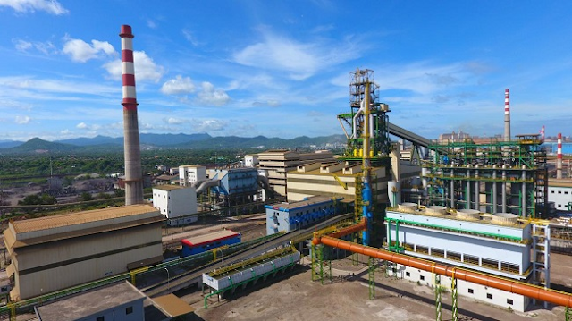
If the new steel plate is patched and the original cracks are not treated, high-temperature and high-pressure gas will flow between the new steel plate and the furnace shell. Not only will the original cracks continue to increase, but also the blast furnace gas will act on the welds. If the welding quality is not good (two pieces) The steel plate steel grade is different, the welding rod is not matched, etc.), it is more likely to cause the weld to crack, the high pressure and high-temperature gas rush out, the cracks and welds are blown up, and the hot coke runs out, causing major accidents.

If you are interested in the blast furnace, please send your tech requirement to marketing2@hanrm.com, our technical engineers will make the customized solution and quotation for you.

Friday, July 23, 2021

Causes and Preventive Measures of Steel Leakage in Continuous Casting Machine

Steel leakage

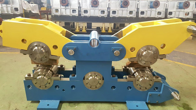
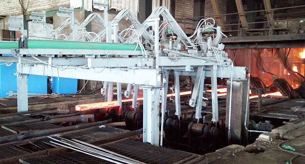
One of the main operational faults encountered in continuous casting is "steel leakage". When the shell of the casting billet breaks down, the static molten steel in the shell overflows and blocks the machine, which requires expensive shutdown costs. In order to pull out the billet shell, the stop time caused by the steel leakage should be extended, because it may block the guide roller or foot roller. It needs to be cleaned and blocked by gas cutting and pulled out the blank shell. 

When the missing billet shell temperature decreases, it needs to be cut into small pieces and taken out of the machine by a straightener. The straightener is designed to straighten the curved cold billet shell gradually in a stable stage. The upper roller can provide enough lifting gravity to make the bending casting flow not too long. Therefore, the steel leakage has a significant impact on the effectiveness of the continuous caster - affecting productivity and production cost.

billet caster

Influencing factors of steel leakage:

1. Temperature and pulling speed are not consistent.

The higher the superheat of molten steel, the thinner the thickness of the shell. Due to the static pressure exerted by the molten steel in the mould, the shell of the billet expands. When the strength of the shell is not enough, it is easy to leak steel. The inconsistent and uneven temperature has a great influence on the steel leakage. When the pulling speed increases, it is easy to leak steel, because the mould is not lubricated enough, and the fluidity of mould protection slag is poor from the meniscus to the shell/mould wall, and the increase of the pulling speed will lead to the decrease of total heat release. 

The steel leakage is often caused by too high pulling speed. When the billet shell does not have enough time to solidify to the required thickness, or the metal is too hot, this means that the final solidification happens just under the straightening roller. Due to the stress applied during straightening, the shell is torn. When the carbon content of steel is certain, the steel leakage is easy to occur when the temperature is high and the pulling speed is fast. Any change in the vibration setting will cause steel leakage, because the way of reducing the vibration mark by increasing the vibration frequency will increase the moulding rate and increase the friction at the interface.

2. Poor lubrication between mould and billet shell 

If the poor quality protection slag is used, the steel under the meniscus is easy to contain slag, which leads to the bond between the mould and the shell, and the blank drawing is interrupted, and the suspension steel leakage is caused. During continuous casting, due to poor lubrication or uneven lubrication, the shell of the billet is bonded to the mould, which affects the heat transfer, resulting in bonding and steel leakage.

3. The method of adding the protective slag is incorrect 

Because of the working habits of the workers on-site, too much is added at one time, and the main arc is concentrated in the arc, which is the slope, which will cause uneven filling of liquid slag, which will affect the lubrication and uniform heat transfer between the mould and the shell. Under normal pouring conditions, it is unnecessary to remove the small slag strip. It is forbidden to use the slag bar to test whether the slag strip is formed in the mould, which will damage the uniform formation of the initial shell of the meniscus.

4. Ineffective flow in the mould 

Reducing the flow into the mold will lead to a reduction of heat transfer, resulting in the formation of a thin shell, and eventually steel leakage. The temperature, pressure and flow rate of the inlet and outlet directly affect the cooling of the crystallizer. The pressure increases and the flow rate decreases due to the blockage of the cooling system of the crystallizer, which affects the heat transfer and easily causes steel leakage. Therefore, the great difference of water temperature (high temperature) at the inlet and outlet leads to the bond between the mould and the shell, and the steel leakage is easy to be broken.

CCM strighter

5. Improper mould geometry 

In order to increase the contact surface of molten steel mould and adjust the taper of the mould to adapt to the solidification shrinkage of steel, thus increasing the heat transfer of the mould and increasing the thickness of the shell. For the traditional mould with linear taper on a high-speed billet continuous caster, the heat transfer at the meniscus makes the casting flow solidify into a solid shell rapidly. With the shrinkage of the shell, the corner is separated from the mould and the heat transfer stops. Therefore, at the bottom of the mould, the shell continues to grow except for the remelting of the corner. When the shell leaves the mould, the temperature of the shell changes greatly, and the increase of the pulling speed may lead to steel leakage. If the taper is not satisfied, an air gap will be generated between the mould and the shell. When the resistance of air to heat transfer in the mould reaches the maximum, it will seriously hinder the formation of the required thickness of the shell, and eventually lead to steel leakage. The taper loss of mould caused by wear and deformation will result in a significant increase in the longitudinal crack of the corner, which is due to the reheating of the corner. 

As far as the mould deformation is concerned, the reason is that the thickness of the copper plate is thin, which is not enough to support the thermal expansion of the copper plate. It may also be that when the ingot bar is inserted into the mould, the lower part of the mould will be damaged and the mould will be deformed. The taper of the mould increases the drag of the blank drawing, which leads to the increase of mould wear. The thickness of the air gap increases with the increase of taper and heat shrinkage, and then the wear of the large corner is added. Therefore, the heat transfer which causes the surface temperature to rise should be reduced. This phenomenon always accompanies the hydrostatic pressure of steel, which will induce tensile strain on the corner surface, which leads to cracks. This kind of crack will reduce the thickness of the shell by fixing, which may lead to steel leakage. The larger the radius of the mould fillet, the larger the air gap. The air gap hinders the heat transfer, which leads to the formation of thin billet shell, which is easy to leak steel. In slab/bloom caster, four separate copper plates are fixed to form holes around them. If there is air gap between the two copper plates, the initial metal will penetrate the air gap and start to solidify, and cause suspension in the later stage, leading to steel leakage. Therefore, improper adjustment of the crystallizer will affect the heat transfer mechanism and cause steel leakage.

6. The steel level in the mould is not suitable 

During continuous casting, the steel level in the mould should be maintained at 70% - 80% of the mould height. If the steel level falls below the immersion nozzle, the solidified shell formed by the subsequent addition of molten steel is thinner and easy to leak. Steel level drop may occur during the plugging of the water inlet, tundish or tundish. When the molten steel is restricted from the tundish to the mould, if the pulling speed is not adjusted, the steel leakage may occur. Therefore, if the control of plug rod is not suitable, the rotation causes the steel overflow, and the sticking to the top of the mould will cause suspension and block drawing, and lead to steel leakage. The decrease of steel level will also cause slag inclusion. If there is sufficient time for the plug bar to close the immersion nozzle, the steel level can be reduced to below the allowable limit. If the pouring starts again, the molten steel will inhibit the mold protection slag, resulting in slag inclusion. 

Therefore, when the ladle is completely cast, the steel level of tundish will drop. If the operation is not correct, the slag can enter the steel water in the mould through the immersion nozzle. The oxidation products of steel flow, improper deoxidation products, and high viscosity slag formed by the high Al2O3 caused by improper spraying of aluminium wire in billet mould may infiltrate into the shell to form slag inclusion, locally inhibit the formation of billet shell, reduce the lubrication between the shell and the mould, and easily bond, which will lead to the interruption of drawing billet and steel leakage. For the automatic control system of the diameter nozzle, the instability of the molten steel level in the mould will cause the fluctuation of the pulling speed, which will affect the stable filling of the slag into the mould and the shell, destroy the continuity of the slag film, and easily make the thickness of the shell uneven, and cause the surface depression or corner crack and steel leakage. The liquid level fluctuates greatly when replacing the immersion nozzle in production, and it also easily causes corner crack or slag leakage.

7. Eccentric pouring flow in the tundish 

The eccentric pouring flow of tundish leads to uneven heat transfer, uneven thickness of solidified shell, decrease of strength at the weak part of billet shell, and it is difficult to bear static pressure of molten steel, so steel leakage is caused. The misalignment of immersion nozzle, the center of steel flow is slanted, the local erosion of billet shell is serious, the uniformity of cooling of the shell in the mould will be greatly affected, and the steel leakage will also be caused when it is serious. The tundish shell is easy to deform locally for a long time, which causes the water inlet to be out of alignment or the insertion depth is not uniform; Improper installation of upper water inlet and block during repair and tundish will also cause the misalignment of immersion nozzle. In production, the center of the nozzle can be judged by comparing the vibration mark depth of the surface of the billet shell.

8. The air mist cooling nozzle is blocked 

The foot roller area is located under the mould, and the water is directly sprayed on the shell through the nozzle. The blank shell is under the pressure of the roller, making the shell smoother. At this time, the heat transfer is the largest, which is convenient to form a thicker shell. If the nozzle is blocked, the thickness of the shell will become thinner, which will easily cause steel leakage. In case of blockage, external force shall be applied by pulling roller. If the limit is exceeded, the surface of the shell will be broken and steel leakage will be caused.

continuous casting

9. Ingot bar irregularity 

Once the molten steel solidifies above the ingot bar of the mould, forming a blank shell of sufficient thickness, the ingot bar will be pulled out slowly. If the ingot bar is not pulled out according to the rules, steel leakage will easily occur. Similarly, the poor assembly of the dummy bar will cause the molten steel to flow out of the mould, leading to steel leakage. If the ingot bar is separated from the shell before the head of the dummy bar is lifted, it will lead to steel leakage.


According to the appearance of the shell, the steel leakage is divided into the following categories:

10. Suspension or bonding causes steel leakage 

The water of steel is bonded to the mould, and therefore is called bonding or hanging. This may be caused by improper lubrication between the mould and the shell or improper adjustment of the mould. The improper lubrication may be caused by the poor quality of the protection slag, slag inclusion in the shell of the mould, overflow of the molten steel of the mould, corner joint of the mould, and poor/unequal operation of the billet caster.

11. The cracks cause the steel leakage 

Longitudinal crack at the corner of the shell and the longitudinal crack in the wide plane will cause steel leakage. If longitudinal crack causes steel leakage, the flow of the slag is uneven, the uneven heat transfer of the mould results in the uneven thickness of the shell, improper selection of the protection slag and uneven cooling of the mould causes the shell rupture during cooling. For the steel leakage caused by a diagonal longitudinal crack, the shell with insufficient solidification thickness along the narrow surface of the mould breaks due to the tensile stress when it contracts. The tensile stress is caused by the decrease of taper of the narrow surface and uneven heat transfer on the narrow surface of the mould.

12. Slag inclusion and steel leakage 

The heat transfer is reduced due to the inclusion of protective slag or large particle inclusions in the shell, which leads to the formation of a thin shell and steel leakage. During billet continuous casting, secondary oxidation products, improper deoxidation products in high viscosity slag during low carbon steel smelting, improper injection of aluminium wire in the mould cause high Al2O3, which all promote slag inclusion in the shell, inhibit the growth of billet shell and cause steel leakage.

13. Thin shell steel leakage 

The observation of such steel leakage in billet caster is caused by uneven thickness of billet shell in the mould, which may be caused by eccentric casting flow in the mold or serious deformation of cooling pipe of mould.

14. Stop pouring causes steel leakage 

The continuous casting process breaks and fails to break the stop pouring. If the joint point cannot bear the pull force imposed by the recasting, the whole furnace steel will leak.

flame cutting machine

The measures to control the steel leakage should take necessary measures to control the occurrence of the steel leakage, considering the influence of the steel leakage on the utilization and effectiveness of the continuous casting machine.

● Only temperature measurement shall be conducted after argon blowing on the pouring platform to ensure the uniformity of temperature.
According to the chemical composition of steel, the pouring flow temperature must be kept over temperature of about 60 ℃ to place the ladle on the rotary table to ensure that the molten steel overheated 25-35 ℃ in the tundish.

● Control the speed of pulling according to the temperature monitored in the ladle. 

The carbon content in steel is fixed one by one to ensure that the temperature increases with the decrease of the pulling speed and the pulling speed increase with the decrease of temperature. Therefore, the pulling speed should be adjusted correctly according to the temperature and carbon content of the steel. The speed of the continuous casting is increased gradually, and the steady continuous casting is maintained by a certain pulling speed. Any interruption in continuous casting should reduce the speed of pulling.

● Any protective slag has a valid period, so it should not be used after the expiration date. 

The protective slag can only be opened during casting and dried under a high wattage bulb. The protective slag of the open bag shall not be used in casting again. Select the appropriate protective slag according to the specified chemical composition of the steel. At the beginning of casting, initial protective slag with low viscosity and low melting point shall be used. For billet caster, it is necessary to ensure that linseed oil is distributed evenly in mould.

● For slab/bloom caster, measure the thickness of slag pool to determine whether the thickness of slag pool is more than 10 mm and the equipment stroke composed of steel, copper and aluminium wires attached to the steel plate, which helps to avoid uniform lubrication of slag inclusion and shell.

● For a high-speed billet caster, various taper crystallizers can be used instead of traditional linear taper crystallizers. To check the mould deformation (if any). The taper of the mould is selected and the taper is adjusted according to the steel rhyme grade and the solidification mode of the mould on the slab/bloom caster to adapt to the narrow surface.

● Before the continuous casting, check the water flow in the mould and find out the blockage (if any) by measuring the increase of water pressure.

In general, check the difference of water temperature, pressure and flow at the inlet and outlet, and flow equipment. The water quality should also be checked. According to the grade of steel and its solidification mode, the cooling mode of mould, i.e. water flow rate (1 / min), is adjusted to adapt to various mould surfaces. In order to control the bonding, the thermocouple was used to detect the change of mould wall temperature and reduce the pulling speed to make the shell grow evenly. For a given caster, ensure that the inlet and outlet water temperature difference cannot exceed the specified value during continuous casting.

● Ensure that the maximum radius of the fillet along the copper plate is 0.2mm. 

If corner joints exist at the copper plate joints, the corner joints shall be filled with gypsum or lime before continuous casting.

● Install the mould level automatic controller on the continuous casting machine to keep the steel level of the mould. 

In order to distinguish the molten steel and slag in the mould and check the slag inclusion, the electromagnetic sensor is installed on the mould.

Before casting, adjust the tundish nozzle and carry out alignment. 

Before the tundish water inlet is blocked, before the ladle is placed on the rotary table, it is necessary to ensure that the wire of Ca Si core is injected into the steel, which meets the requirements of high aluminium steel, so as to form low melting point calcium aluminate. Use a cryostat to avoid the rod from turning.

● By using metal protective flux in tundish and shielding plate between ladle and tundish, it is necessary to ensure that deoxidation products are appropriate to prevent the formation of secondary oxidation products. Mn / Si > 3 shall be maintained for the billet caster.

● Seal the spindle rod head with asbestos rope and use the quench box to ensure the correct distribution of the quench box before casting.

● To check the blockage (if any), check the spray cooling nozzle and water flow.

Looking for the continuous caster or relevant spare parts, please mail at marketing2@hanrm.com.

More Articles You May Be Interested:

Monday, July 19, 2021

Preventive Measures for Induction Furnace Leakage and Wear Accidents

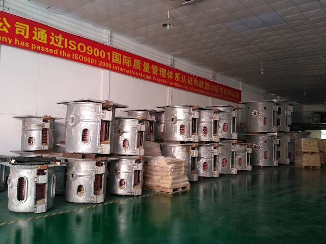
The working temperature of the molten metal core of the induction melting furnace can reach up to 1600°C, which is high-risk equipment. Once the equipment, especially the steel shell furnace body, fails, it may cause major accidents. Therefore, it is of great significance to do a good job in the maintenance of the induction furnace from the details, and to understand the basic safety protection knowledge of the foundry melting furnace.

The common accidents of the furnace body of the crucible induction furnace include furnace leakage and furnace wear. If an accident occurs, if no measures are taken, it will cause the copper tube of the coil to rupture, the molten iron and the coolant will explode, which will cause major equipment accidents or personal injuries. Therefore, it is very important to clarify the cause of the accident, preventive measures and emergency measures after the accident.

induction furnace

1. Reasons for furnace leakage and furnace wear accidents

(1) The molten iron cools for too long and the lid is formed. It expands when heated again, and the lining is extruded to cause cracks in the lining. During the melting process, the molten iron penetrates through the cracks, causing the furnace to be worn or sprayed from the lid, causing a furnace injection accident.

(2) As the furnace age increases, the volume of the furnace lining becomes larger, the amount of molten iron in the furnace increases, the furnace lining is thinner, and the furnace cannot withstand the pressure of the molten iron locally, causing the furnace to wear.

(3) When the furnace lining is knotted, it partially fails to meet the requirements or partially brings in impurities and is not found, causing the above-mentioned defects to be penetrated during smelting.

(4) The rapid cooling of the furnace lining produces cracks, which penetrate through the cracks during the smelting process.

2. Preventive measures

(1) From the beginning of the furnace construction, a dedicated person must be strictly managed to ensure that the knots of each furnace lining are consistent. It is forbidden for sundries to fall into the furnace lining when knotting.

(2) Before each feeding, observe whether there are cracks in the furnace lining, perforation, etc., which may cause the furnace to penetrate. Once there is a problem, it must be dealt with.

(3) During the smelting process, due to equipment failure or other factors, the furnace cannot be opened for smelting for a long time, the molten iron should be turned out of the furnace to prevent cap formation.

induction melting furnace

During the smelting process, if the furnace body of the induction furnace has a furnace leak, it will cause heavy losses. Not only the entire furnace steel (iron) water will be scrapped, but the heart (inductor) of the furnace body will also be burned or even scrapped, and personal accidents may also occur. Therefore, in order to avoid unnecessary losses and affect production, it is very important to avoid furnace leakage when using induction melting furnaces. Generally speaking, the device leakage detection and alarm device is a necessary measure to ensure the safe operation of inductotherm induction furnaces and avoid the expansion of the incident.

Now, there is a way to install a stainless steel sheet (or disposable stainless steel wire mesh) on the inner side of the induction coil as the second electrode. The claws made of 6 to 7 stainless steel wires touch the liquid metal as the top electrode. If the molten metal penetrates the furnace lining and touches the stainless steel sheet (or stainless steel wire mesh), the leak detection alarm device will announce the leak alarm.

If you are interested in induction furnace, please mail at marketing2@hanrm.com for your solution.

More Articles You May Be Interested In:

Comparison of Electric Furnace, AOD furnace, LF furnace and VD Vacuum Furnace

Short-process Electric Furnace Steelmaking and Continuous Casting

Important Cautions for Use of Intermediate Frequency Furnaces

Energy-Saving Technology for Heat Treatment of Induction Furnace

Roller Hearth Reheating Furnace

Classification of Electric Arc Furnace

Melting Features of Medium Frequency Electric Furnace

Electric Arc Furnace VS Intermediate Frequency Furnace

Why Intermediate Frequency Furnace cannot be Turned on Normally?

Energy-Saving Technology for Heat Treatment of Induction Furnace

Cause Analysis and Solution of Induction Coil Blocking in Medium Frequency Smelting Furnace

Characteristics of Electric Arc Furnace Steelmaking

What is Induction Furnace?

Significance of Reheating Technology in Rolling Reheating Furnace

How to Improve the Thermal Efficiency of the Reheating Furnaces?

What is the Reheating Furnace Temperature System?

The Advantage of Induction Furnace (Medium Frequency Furnace)

On the Advantage and Disadvantage of Electric Arc Furnace and Induction Furnace

Wednesday, July 7, 2021

Design of Continuous Casting Machine Foundation

The design of the continuous casting machine foundation is the basic structure design that supports and fixes the continuous casting machine and its related equipment, and transmits various loads and the dynamic loads of the equipment to the foundation through the foundation. The foundation of the continuous caster usually refers to the foundation of the ladle turret, intermediate tank, crystallizer, tension leveling device and shearing machine. Some of the columns of the continuous caster steel platform are also fixed on it. The main contents of the design include the collection of original data, basic form, basic calculation and basic structure.

The basic type of continuous casting machine has a variety of models such as vertical continuous caster, vertical bending, horizontal continuous caster, arc and multi-point bending. Continuous casting methods are divided into single-stream and multi-stream. Casting products include slabs, square billets, round billets and octagonal billets. The operation of casting billets is generally carried out by placing the ladle on a turntable or directly hoisting the ladle on a crane. Therefore, the basic forms are also different.
continuous caster

The structure of the foundation of the continuous caster is more complicated. From the ladle turret to the foundation of the shearing machine, the height is uneven. According to the design of some projects, the top level of the foundation is as high as 10~15m, and the height of the base is 5~-8m. Trenches and cable tunnels are arranged in the foundation (see picture). The load of each part of the foundation is quite different. Therefore, it should be based on the foundation design plan (such as natural foundation or pile foundation, etc.), the layout of process equipment, the distribution of the load of each part, the layout of the channel in the foundation, and the relevant design specifications. The specified allowable maximum length of the foundation and other conditions, reasonably determine the location of the foundation deformation joints. The foundation of the continuous caster is a mixture of block type, wall type, frame type, box type, pit type, beam, plate type and other structural forms.

The loads and external forces acting on the foundation include:

(1) The weight of the equipment acting on the foundation and the structural dead weight from the steel platform of the continuous caster and the weight of the equipment acting on the steel platform, and the single molten steel when the continuous casting machine is running. The deadweight, molten steel weight and operating load of the ladle and double ladle.

(2) Horizontal force, bending moment and torque generated during equipment operation.

(3) The external force generated by abnormal operation during the production process, for example, the vibration caused by the unstable operation when the ladle is placed on the turntable. In this case, the weight of the molten steel and the ladle is generally multiplied by the power coefficient. Since the ladle can change positions on the turntable, the unfavorable load combination generated when the ladle is at different positions must be considered.


The calculation points of the foundation are as follows:

(1) When the various parts of the foundation of the continuous caster are decomposed into wall, frame, box, pit or beam-slab components, the internal force and reinforcement must be carried out according to their actual stress conditions. (2) When the cable tunnel and the water trench are located at the edge of the foundation, where the trench wall is thin, and the groundwater level is higher than the bottom elevation in the trench, the influence of groundwater pressure on the bearing capacity of the trench must be considered and the crack width must be checked.

(3) The center of gravity of the applied load, the weight of the overburden and the weight of the foundation and the centroid of the bottom of the foundation should be located on the same vertical line as far as possible. Check the bearing capacity of the foundation based on the above loads.

(4) When the foundation of the continuous casting machine is built in the seismic fortified area, the seismic check calculation must be carried out. When the foundation is built on a soft soil site, pile foundations or other artificial foundations can be used.

continuous casting machine

The basic structure of the continuous caster is mainly as follows:

(1) The ladle turret and its supporting frame or wall underneath are generally subjected to high strength, so the concrete with strength grade C25 or C30 is generally adopted the continuous caster foundation adopt C20 or C25. Concrete.

(2) The foundation is made of ordinary reinforced concrete. On the top of the ladle turret, it is necessary to locally build refractory bricks vertically and horizontally to insulate the foundation body according to the requirements of the process. When the refractory bricks are erected vertically, they need to be tied with the embedded steel bars of the foundation.

(3) The anchor bolts of the equipment are mostly deadbolts buried at one time. In the range of the ladle turret platform, T-head live bolts are generally used. For large continuous casting machine, prestressed bolts should be used. Since bolts are mostly made of high-strength steel, electric welding and fire are strictly prohibited during construction and installation.

(4) Reasonably choose the location of construction joints, and it is not advisable to set up more construction joints to facilitate the integrity of the foundation. During construction, it is necessary to take appropriate measures according to the construction season to avoid shrinkage cracks during concrete pouring.

(5) Settlement observation points should be embedded in the four corners of the foundation exposed to the ground.

Looking for the continuous caster or relevant spare parts, please mail at marketing2@hanrm.com.

More Articles You May Be Interested:


Four Processes of High-speed Steel Manufacturing

High-speed steel can be divided into traditional casting technology, electro slag remelting technology, powder metallurgy technology, and sp...